Start » Street Car+Patente » 1926 Patent Martin Itjen Hebevorrichtung US1579539 A
April 6. 1926, 7 v 1,579,539 (Application filed October 22., 1925. Serial No. 64,197)
MARTIN ITJEN and GEORGE TONY RAPUZZI, citizens of the United States, residing at Skagway, Alaska, have invented certain new and useful Improve the forward end of the lifting lever, a HOISTING DEVICE.
Patented Apr. 6, 1926, US 1579539 A
UNITED STATES, MARTIN ITJEN AND GEORGE TONY RAPUZZI,
SKAGWAY, ALASKA, A HOISTING DEVICE.
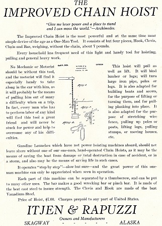
A further object is to provide a hoisting device of. The above mentioned character which is simple in construction, inexpensive, strong and durable and further well adapted to the purpose for which it is designed.
Other objects and advantages of the in vention will be come apparent during the course of the following description taken in connection with the accompanying-drawing.
In the accompanying drawing forming a part of this application and in which like numerals designate like parts throughout the same:
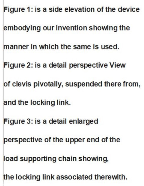
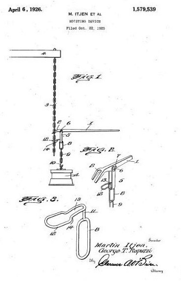
In the drawing, where in for the purpose of illustration is shown the preferred embodiment of our invention, the numeral 1 designates an elong ated lever, the forward end of which is provided with the downwardly disposed claw2 which is adapted for engagement with the link of a suitable chain 3 which is suspended from a stationary support 4 at its upper end. The purpose of this claw will be here in after more fully described.
Substantially clevis 5 is to improvements the free end of the chain.
Application filed October 22, 1925. Serial No. 64,197
Suspended from the lever 1 at a point adjacentthe claw 2 and to this end there is provided a bolt 6 which extends transversely through the forward portion of 60.
The lever and through the upper free ends of the arms of the U-shaped clevis. A suitable wing nut 7
is associated with the threaded end of the bolt-in the manner clearly shown in Figure 2.
This clevis extends through an enlarged link 8, which forms the upper most link of the load supporting chain 9 the latter having a hook 10 associated with the lower end there of for engagement with the article or object 0 to belifted. An extension in the form; of an arm 11 is formed on the upper end of this enlarged link 8 and said extension is disposed between the arms of the U-shaped clev is 5, as clearly shown in Figure 2.
An additional enlarge. 12 has its her end reduced or restricted to providela neck portion 13, the purpose 'of which will be presently apparent. This last mentioned link is termed forthe purpose of convenience, a locking link; The locking link is secured to the upper end of the extension orarm 11 in any suitable manner so as to cause a locking link to be dispo-sedat substantially right angles to the enlarged link 8 and as is further illustrated in the drawing.The arms or sides of the locking link are disposed in a horizontal plane. The locking link is furthermore offset at the juncture of the neck portion 13 with the main body portion of the link, as illustrated at 14. This locking link has its neck portion disposed between the arms of the U-shaped clevi's 5 and the major portion of said locking link 7 forward end of the elongated lever for cooperation there with in the manner to be is disposed below the claw 2 formed on the presently described.
In use, the hook of the load supporting chain 9 is securedto the object to be lifted, in the present instance noted by the letter 3 extends through the outwardly disposed portion of the link 12. In order to lift the load, the free end of chain 3 is moved in wardly so as to cause one of the links there of to be 7 disposed within the neck portion 13, when in this position the free end of the lever 1 is swun downward so as to cause the forward of the lever aving the claw 2 formed there on to be raised. This will permit the claw to move upwardly on the the lifting means and easily brought into operative position.
"he used for tightening and we do not wish to limit ourselves to the particular use tor which the device 1s and permit the load toagain he raised a slight distance.
In this niner, a step by step arrangement is provided for raising a load and provision of a hoisting device of the above mentioned character will prevent any possibhility of the load being accidentally dropped after it has been raised. For holding the load in a suspended position while is actuated, being readily a device of this character may not only be used as a hoisting device, but may also chains or as a binder, adapted.
While we have shown the preferred emhodiment our invention it is to be understood that minor changes in the size, shape and arrangement of parts maybe resorted to without departing from the spirit of the invention and the scope of the appended claims.
Having thus described the inventlon, what we claim as new is 1. hoisting device of the class described comprising a lever, a claw formed on the forwardend there of vand adapted for engagement with a chain suspended from a stationary support, a cievis pivotally suspended from the forward portion of the lever, a load supporting chain having its upper end suspended from the is and a locking link having its inner end secured to the uppermost link of aid load supporting chain, the free end of the first mentioned chain being adapted to extend through said link. The inner end of the link being provided with a restricted neck portion for cooperation with the link of the first mentioned chain in supporting the load in a suspended position while the claw on the lever is moved upwardly on the first mentioned chain to engage an upper link, said first mentioned chain being adaptcdi to he disengaged from said restricted neck portion when the claw has been moved upwardly to facilitate furtherraising it the load.?
A hoisting device of: the class described comprising a lever, a chain engaging claw termed on the forward end there of a substantialiy U-shaped clevi-s having the free ends of the arms thereof pivotally securedto the opposed sides of the forward portionof the lver, a load supporting chain having its uppermost link extending through the crown portion of the clevis, an arm extending upwardly from the upper end of the upper most link oi said load supporting chain, a locking link through which the free end of the last mentioned chain is adapted to ex tend, the inner end of said locking link being provided with a reduced neckportion for cooperation with a link of the first mentioned chain, the inner end of said locking link being secured to the upper end of said arm, said elaw adapted to he inoved upwardly on the first mentioned chain when the links of the chain are held in locked engagement with therestricted neck portion of the lockinglink to perinit the claw to an upper link andenable the lever to be actuated where by to further raise the load.
In testimony, where of we have affixedlour signatures.
MARTIN ITJEN, GEORGE TONY RAPUZZI.
Dieses soll die Patentanmeldung sein.
Mit der Beschreibung könnte ich die Hebevorrichtung nicht bauen.
Wenn es den Kran 1926 noch nicht gab, ist das eine tolle Erfindung und Hilfe gewesen.
Die Reklame GEORGE TONY RAPUZZI